Image Processing on FPGA

This design shows how we can read an image from BRAM, apply visual effects in real time, and drive a display over HDMI using an FPGA.
For this project, I chose to use a photo of myself (from when I was young and beautiful, hahaha), because there’s something special about seeing your own face transformed by hardware you programmed. After converting the image into a .mif file (my_picture_RGB8.mif) and loading it into the FPGA’s Block RAM, I built a series of VHDL modules to apply various visual effects.
It would’ve been easy to use a phone app for similar edits, but creating these effects in VHDL and watching them run on real hardware is a completely different experience. I did really LOVE it. =)))
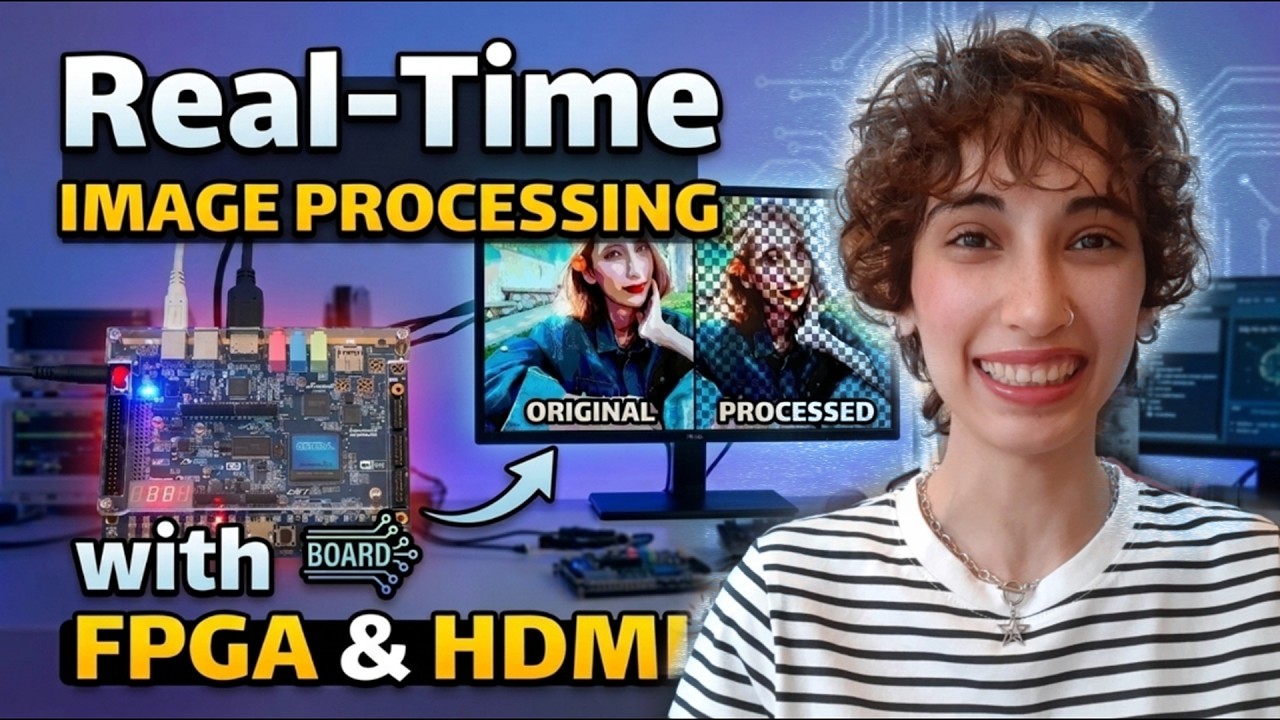
Watch my video on youtube (click on the picture below):
Note!
The demonstration images in this README were captured from the simulator using the full RGB24 color format. Because the Cyclone V GX FPGA has limited Block RAM (BRAM) capacity, I configured the hardware implementation to use a compressed 8-bit (RGB332) format for image storage within the ROM. Although the system expands this 8-bit data back to 24-bit (RGB888) before displaying it on the HDMI monitor, the simulation images maintain higher visual quality because they were processed without any initial color reduction. As a result, while the system functions perfectly in real-time, the colors on the physical monitor may appear slightly less vibrant than those seen in the high-fidelity simulation results.
Project Overview
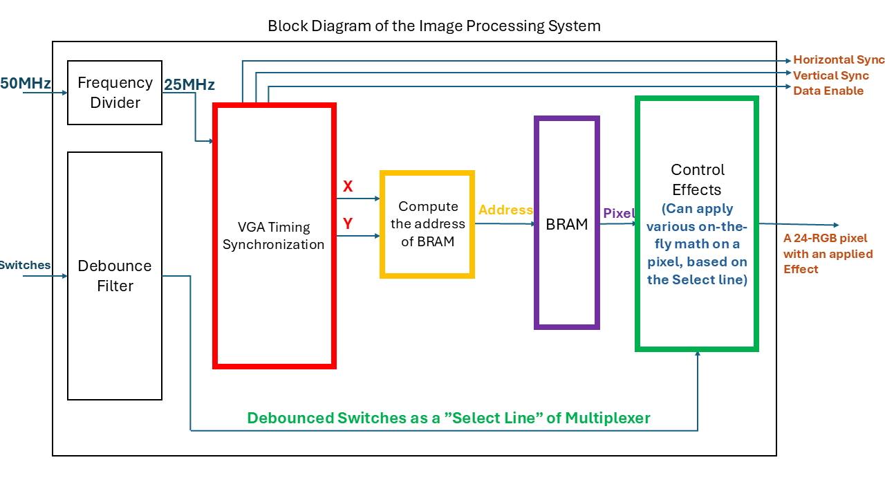
This project is a hardware image-processing pipeline built in VHDL. It stores a static image in BRAM, reads pixels in sync with display timing, converts the stored compact color format into a full-color representation, and applies one of many visual effects before sending the result to a monitor.
The image is first converted by Python into a small 8-bit RGB332 format and stored as a .mif file. In the FPGA, each pixel is read in real time and expanded into a 24-bit RGB888 color value so the effect modules can process it with greater precision.
The system can display the original image, mirrored image, pixelized image, or many color and stylized filter effects. It also supports simulation for verification before deploying to the hardware.
Effect Module Details
In this digital image processing system, each visual effect is implemented using specific mathematical logic or bit manipulation. The system processes 24-bit RGB data (8 bits each for Red, Green, and Blue) to generate the output for each module.
Below are the formulas and logic used for each effect:
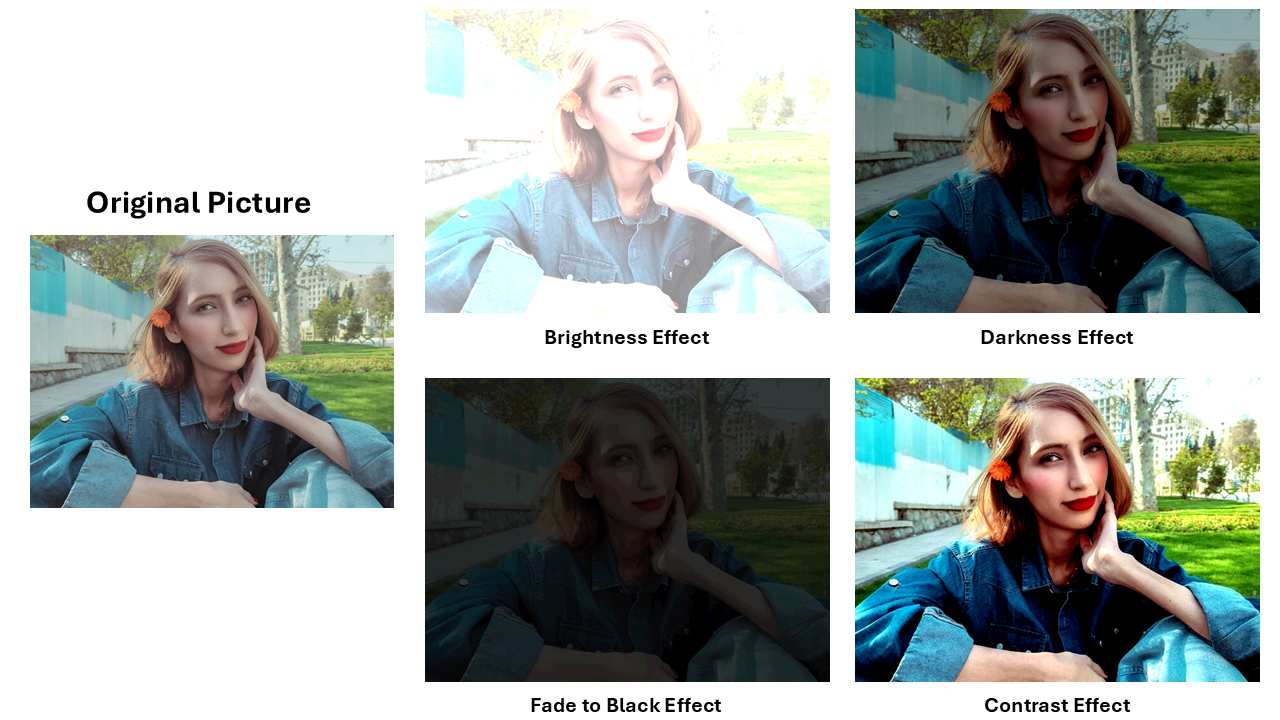
Intensity and Contrast Effects
- Brightness (
rtl/effects/effect_bright): Each color channel is increased by a constant value (g-BRIGHT = 128). The system adds this to the input and “clamps” the result at 255 to avoid errors.
Channel_out = Channel_in + g-BRIGHT
- Darkness (
rtl/effects/effect_dark): This is the opposite of brightness. It subtracts a value (g-DARK = 128) and ensures the result does not go below 0.
Channel_out = Channel_in - g-DARK
- Contrast (
rtl/effects/effect_contrast): This increases the difference between light and dark areas. It uses a midpoint (128) and a multiplier (g-CONTRAST = 2).
Channel_out = 128 + (Channel_in - 128) * g-CONTRAST
- Fade (
rtl/effects/effect_fade): This reduces the intensity of the image by keeping only the most significant bits and masking the rest. It essentially “mutes” the colors by shifting the data.
Channel_out = (Channel_in AND 11100000)
Black-white and Grayscale Effects
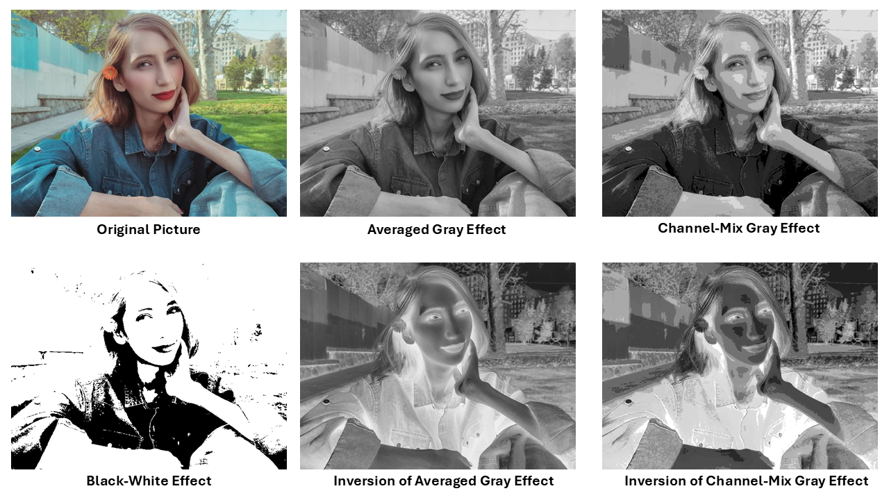
- Grayscale Averaged (
rtl/effects/effect_grayscale_averaged): It calculates the average of all three colors to find the brightness level.
Gray = (Red + Green + Blue) / 3
Output of all channels = ( Gray )
-
Grayscale Channel-Mix (
rtl/effects/effect_grayscale_channelMix): Instead of math, it creates a gray look by taking specific high-order bits from Red (bits 7:5), Green (bits 7:5), and Blue (bits 7:6) to form a new 8-bit signal. -
Inverted Grayscale (Averaged/Channel-Mix): These modules calculate the grayscale value first and then apply the “Negative” formula (NOT Gray).
-
Black and White (
rtl/effects/effect_BW): This compares the total brightness to a threshold (g-THRESHOLD = 225). If the sum of R+G+B is higher, the pixel becomes pure white; otherwise, it is pure black.
If  (R+G+B) > g-THRESHOLD  then
    Output <= White
else
    Output <= Black
Posterize and Tint Effects
-
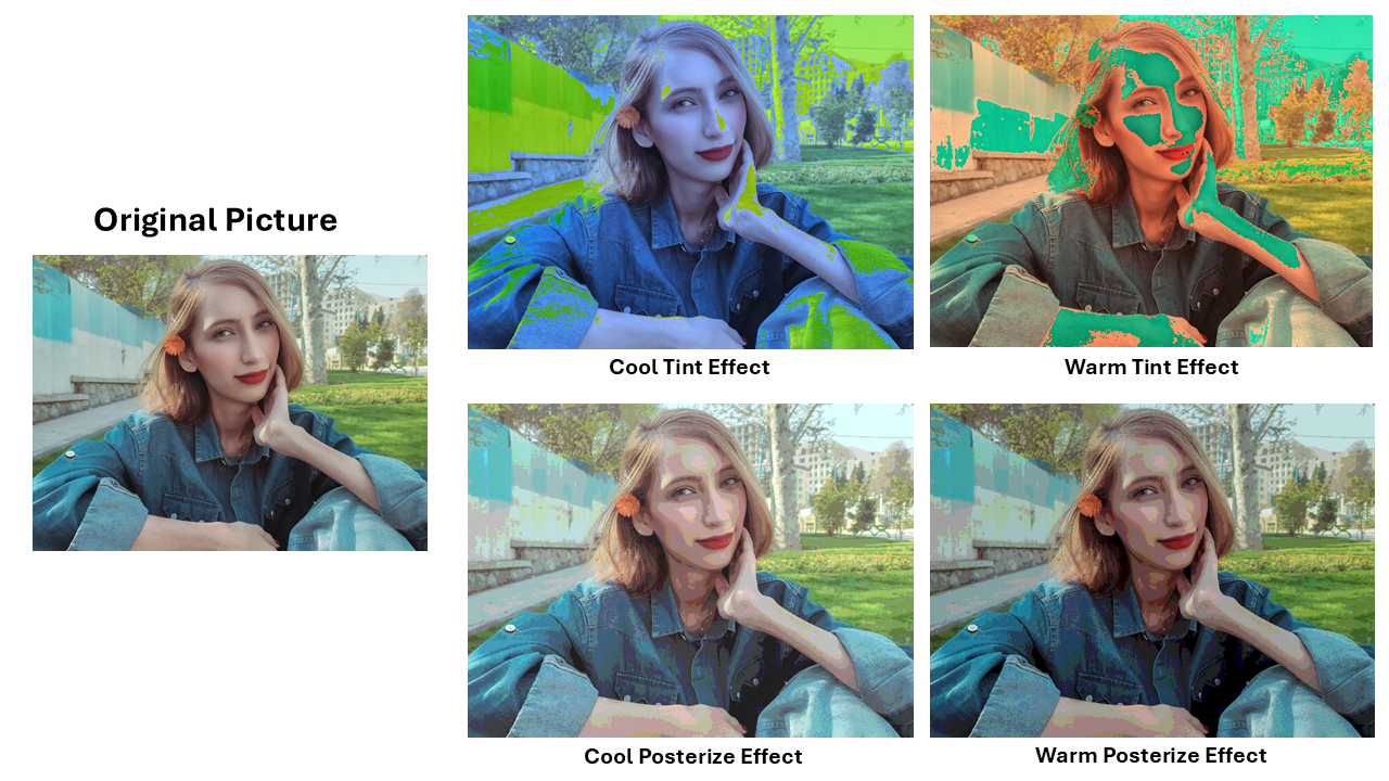
Warm Tint (
rtl/effects/effect_warm_tint): This amplifies the Red and Blue components (specifically using a 3X multiplier in the source) to give the image a “hot” look. -
Cool Tint (
rtl/effects/effect_cool_tint): This favors the blue spectrum by increasing blue-related values and decreasing red-related values. -
Posterize (Warm/Cool): These modules “chop” the lower bits of the color data to reduce the total number of colors (creating a “poster” look) and then apply a warm or cool color offset.
Stylistic and Color Conversion Effects
- Solarize (
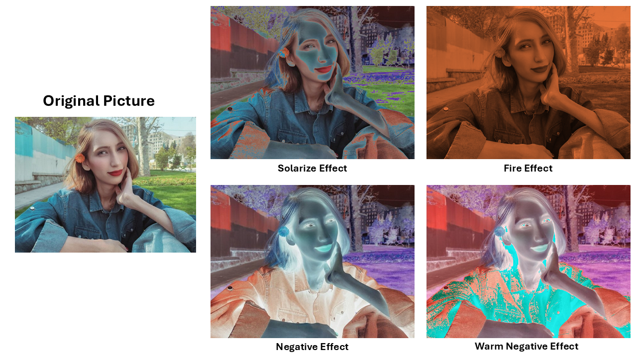
rtl/effects/effect_solarize): This effect inverts a pixel’s color only if it is already very bright (above a threshold of 225).
If  (R+G+B) > g-THRESHOLD  then
    Output <= (255-R, 255-G, 255-B)
else
    Output <= original
-
Warm Negative (
rtl/effects/effect_negative_warm): It first inverts the colors (negative) and then adds a warm tint offset to the result. -
Fire Effect (
rtl/effects/effect_fire): This calculates the average brightness of a pixel and then uses that number to choose a color from a “fire” color ramp (transitioning from black to red, then orange, then yellow). -
Negative (
rtl/effects/effect_negative): This inverts the colors.
Channel_out = NOT Channel_in
Coordinate and Dynamic Effects
- Checkerboard (
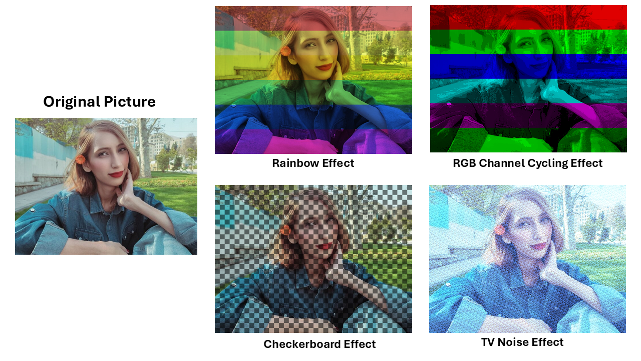
rtl/effects/effect_checkerboard): It looks at the 5th bit of the X and Y coordinates. If you XOR these two bits and get ‘1’, it shows the image; if ‘0’, it shows black. This creates 32 * 32 pixel squares.
if (X(4) XOR  Y(4)) = '1' then
    Output = Image
else
    Black
- CRT Scanlines (
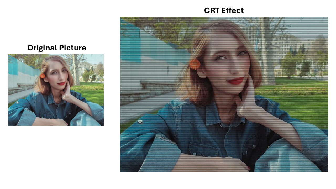
rtl/effects/effect_CRT): This simulates an old TV by making every other line darker. It checks the LSB of the Y coordinate.
If Y(0) = '1' then
    Channel_out = Channel_in / 2
else
    Channel_out = Channel_in
- TV Noise (
rtl/effects/effect_TV_noise): The TV noise effect utilizes an 8-bit Linear Feedback Shift Register (LFSR) to generate a pseudo-random value. Using this value it creates a noise for each channel and then increases the color of each channel by the corrosponding noise. Result is in the appearance of flickering grayscale static on the monitor.
Red-Noise = LFSR / 4
Green-Noise = LFSR / 2
Blue-Noise = LFSR
Channel_out = Channel_in + Noise
-
Rainbow (
rtl/effects/effect_rainbow): This effect applies different color tints in vertical bands. It gives each section a distinct hue: red, orange, yellow, green, blue, and violet. -
RGB Cycling (
rtl/effects/effect_RGB_cycling): Similar to the rainbow effect, but it “rotates” the Red, Green, and Blue channels based on the current row ($Y$) to create a moving color cycle.
Address Manipulation and Expansion Effects
-
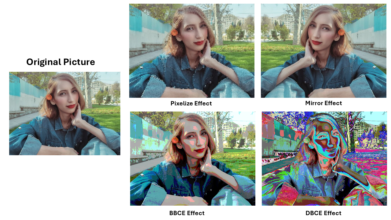
BBCE; Bright-Biased Color Expansion (
rtl/effects/effect_BBCE): This logic expands the color range specifically in the bright areas of the image to make highlights pop more. -
DBCE; Dark-Biased Color Expansion (
rtl/effects/effect_DBCE): This expands the range in the darker areas of the image to show more detail in shadows. -
Mirror Effect (
rtl/logics/read_rom): The Mirror effect creates a horizontal reflection by reversing the order in which pixels are read from each row of the memory. Normally, the system reads pixels from left to right (0 to 639). To mirror the image, the system instead reads from right to left. When the screen wants to display the leftmost pixel (X=0), the system fetches the rightmost pixel from the ROM (X=639).
Address = (639 - X) + (Y \times 640)
- Pixelize Effect (
rtl/logics/read_rom): The Pixelize effect creates a “mosaic” or “blocky” look by forcing the system to display the same pixel value for a small square area (e.g., a 10 * 10 block).This is achieved by “quantizing” the coordinates. Instead of updating the memory address for every single pixel, the system uses integer division and multiplication to group coordinates together. This causes the X and Y values to stay the same for a specific range, effectively “stretching” one pixel across a larger block of the screen.
Address = ( Y(MSB downto 2) & "00" ) * c-IMG-WIDTH + ( Y(MSB downto 2)$ & "00" )
Setup Guide
1) Prepare the Image
- Use the Python script
scrpits/png_to_mif_converter.py. - Convert your source image to 640x480 and your desired color format.
- The script creates
.miffiles such asmy_picture_RGB8.mif. - Place the generated
.miffile in the project directory and store it into BRAM.
2) Compile the code and configure the FPGA
- Open the Quartus project and put the
rtl/files into project dirctory. - Run synthesis and Generate the programming file and program the FPGA.
- Click here to open the Pinout-Table.CSV
3) Select Effects
- Use the input switches to set the effect code.
- LEDs display the current effect bits.
- The image will update in real time when the effect changes.
4) Simulate First (Recommended)
- If you wish to test new effects without using the board:
- Use
sim/img_processing_TB.vhdin ModelSim or another VHDL simulator. ( I used Isim since I’m used to it) - The simulation uses 24-bit color for higher precision.
- The testbench will output a text file of the processed pixels.
- Run the Python script
scrpits/txt_to_png_converter.pyto convert that text file back into a .png image to see your results.