Real-Time Color Tracking System on FPGA

This project implements a specialized Color Tracking System in VHDL for the Cyclone V GX FPGA. The system processes 24‑bit video data and tracks moving objects based on their color. It supports 12 distinct color shades, selectable by the user through on‑board switches.
At the core of the system is a color classifier that identifies colors using intensity thresholds and channel‑gap logic, and a tracker engine that determines the spatial boundaries of the detected object. Once the target is located, the system draws a bounding box around it and displays its exact X and Y coordinates on the HDMI screen.
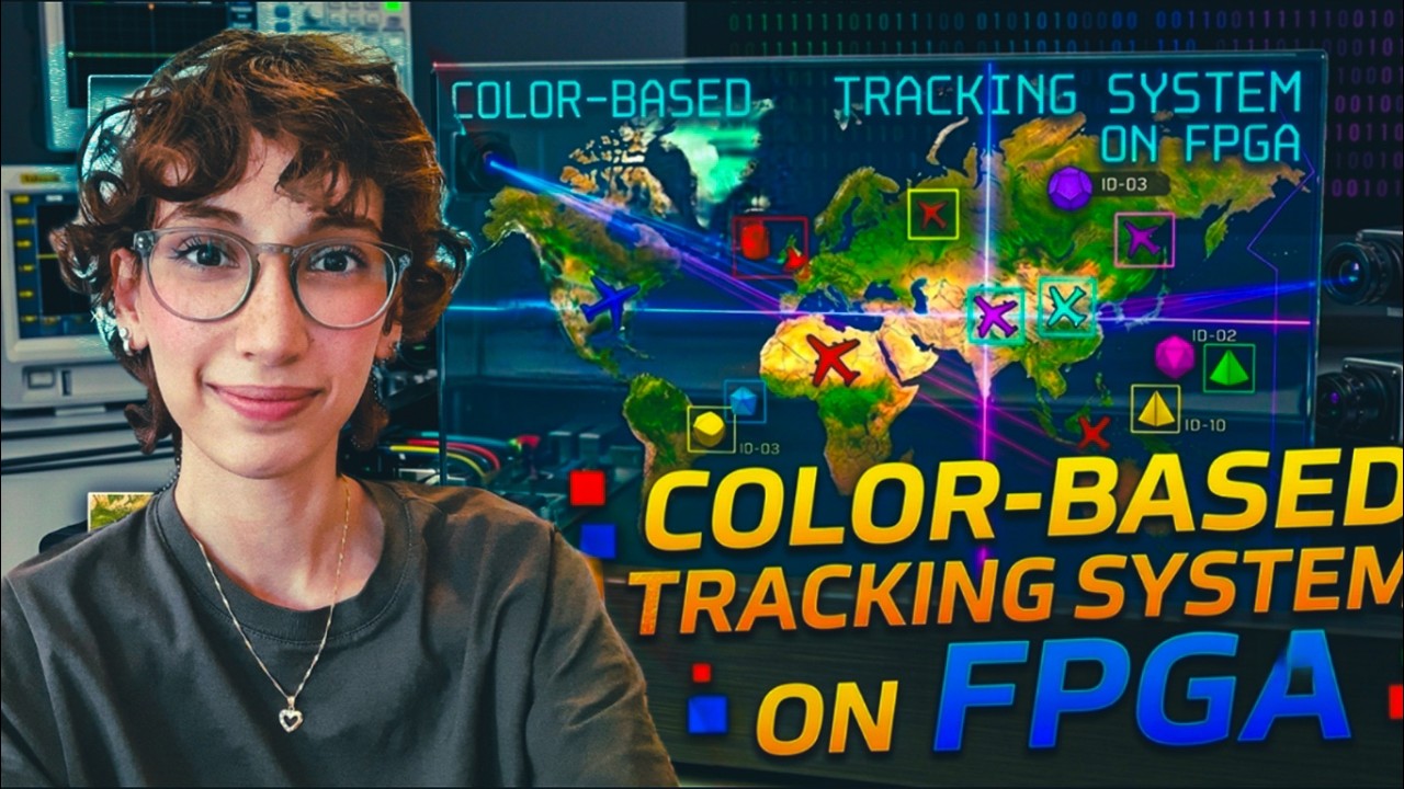
Watch the demo on youtube (click on the picture below):
Module Descriptions and Functionality
Color Classifier (color_classifier.vhd)
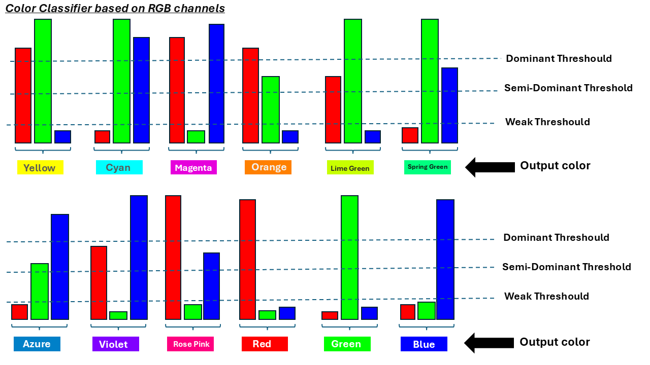
This module is the “eyes” of the system. It Recievers 24-bit RGB data and it classifies it into 12 main colors by checking the strength of each channel.
- Dominant Threshold: If a channel (Red, Green, or Blue) is above 80, it is considered “strong”.
- Similarity Logic: To distinguish between similar colors (like Yellow and Orange), the module checks the “Gap” between channels. For example, in Yellow, Red and Green must both be strong and have a difference of less than 35.
- Differentiation: It also ensures the “weak” channel is significantly lower than the “strong” ones by at least a value of 45.
Tracker Engine (tracker_engine.vhd)
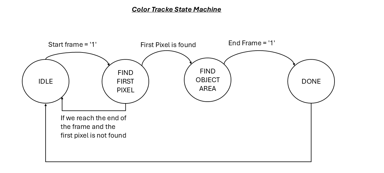
This module manages the logic for finding an object’s location. It uses a state machine with four states: IDLE, FIND_FIRST_PIXEL, FIND_OBJ_AREA, and DONE. As the VGA scan moves across the screen, the engine records the first and last X/Y coordinates where the target color appears, effectively creating a bounding box for the object.
Draw Tracker Sign (draw_tracker_sign.vhd)
Once the Tracker Engine finds the boundaries, this module draws a visual marker. It creates a rectangular border and a crosshair that follows the object with high precision. It also calculates the Middle Point (center) of the object, which is then used for the coordinate display.
Display Coordinate Top (display_cordinate_top.vhd)
This module works as an On‑Screen Display (OSD) controller. It shows the center coordinates of the tracked object in text format.
Double Dabble (double_dabble.vhd)
This module uses the Double Dabble algorithm to convert the binary coordinates into Binary Coded Decimal (BCD). This allows the system to display numbers like “120” instead of binary code on the monitor.
Setup Guide for Rendering and Tracking
To demonstrate how this tracking system works, I created a simple flight radar animation. In this demo, there are 8 planes, each with a different color, moving across the screen. The tracking system can follow any of these planes based on the color you select.
You can render any scene you want and send the 24‑bit RGB video data to the color tracking system. It works with any shapes or objects, no matter how fast they move. The tracker reacts immediately and finds the selected color with high accuracy.
After programming the FPGA, you will see the moving planes on the screen (if you use the flight radar demo). If you render something else, you will see your own animation.
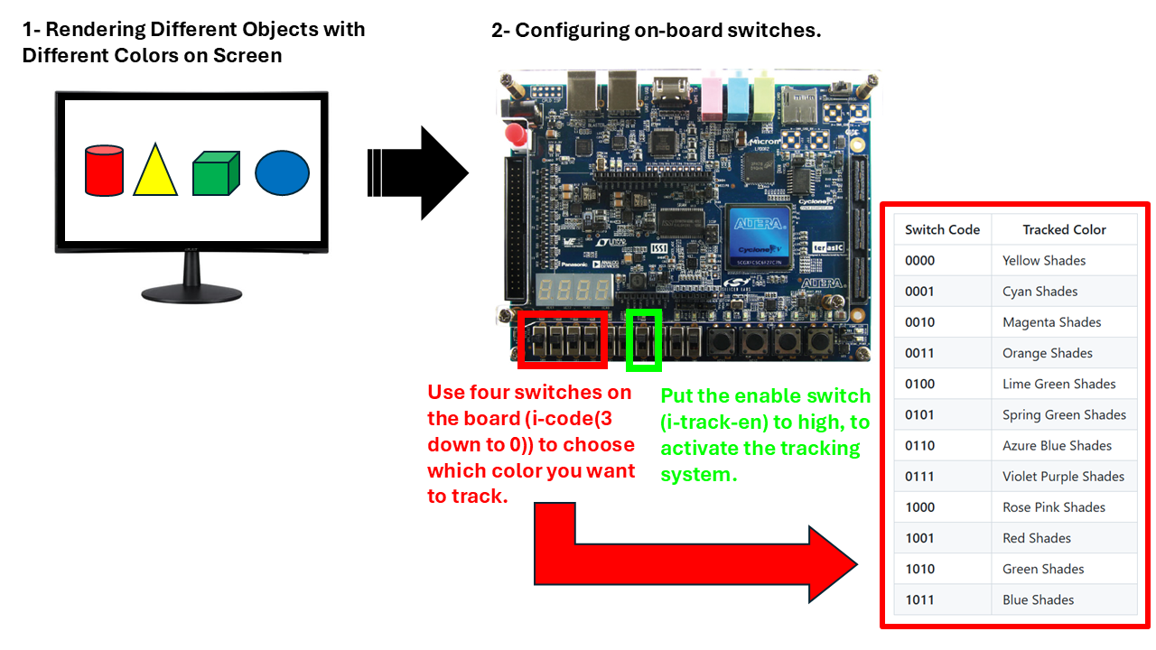
At first, the tracking system is inactive. To activate it, you use one of the board switches (i_track_en). When this switch is high, the tracking system becomes enabled.
To choose which color you want to track, you use four switches on the board(i_code(3 downto 0)).
For example:
- If all four switches are low (
0000), the system tracks yellow. - If the three left switches are low and the rightmost switch is high (
0001), the system tracks cyan.
Here is the full list of color codes:
| Switch Code | Tracked Color |
|---|---|
| 0000 | Yellow Shades |
| 0001 | Cyan Shades |
| 0010 | Magenta Shades |
| 0011 | Orange Shades |
| 0100 | Lime Green Shades |
| 0101 | Spring Green Shades |
| 0110 | Azure Blue Shades |
| 0111 | Violet Purple Shades |
| 1000 | Rose Pink Shades |
| 1001 | Red Shades |
| 1010 | Green Shades |
| 1011 | Blue Shades |
Based on the color you want to track, set the switches to the correct value and enable the tracking system. After that, the tracker finds the object with the selected color and draws a bounding box around it. It creates a rectangular border and a crosshair that follows the object with high precision.
The system also applies a green effect to all pixels that are not part of the tracked object area. This helps the user focus on the detected object by making the rest of the screen green, except for the tracked color.
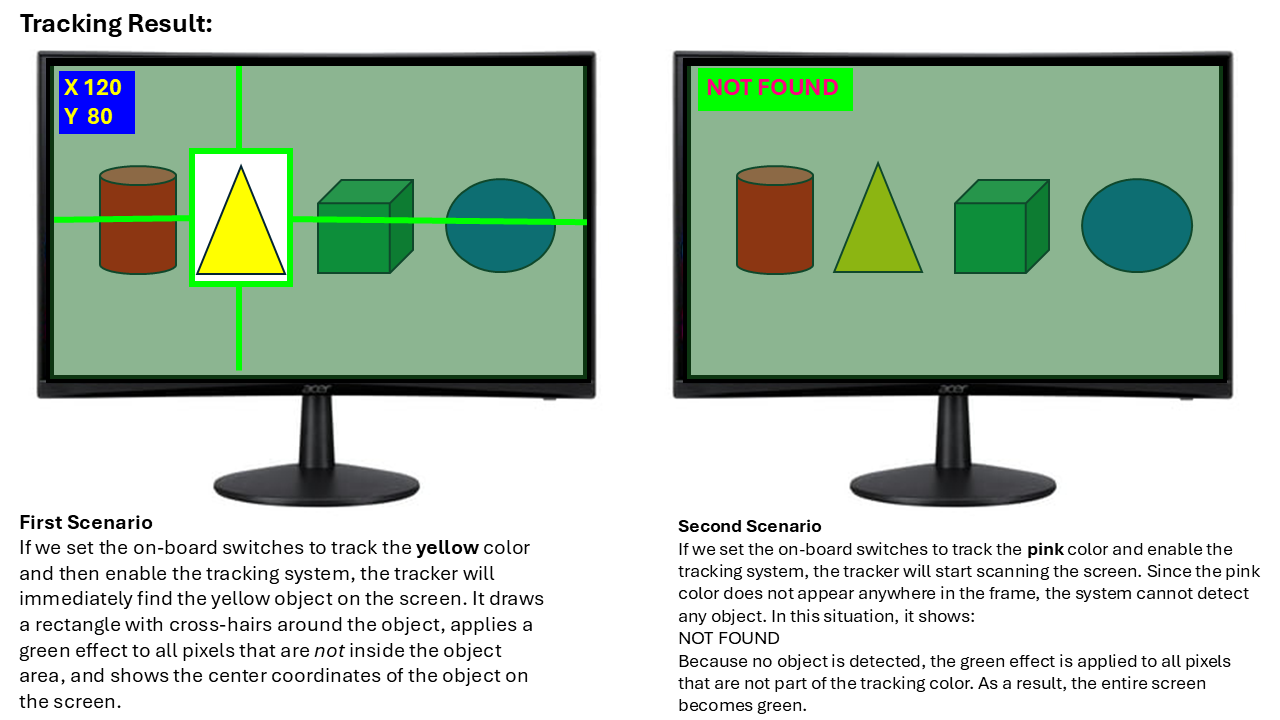
The tracker also displays the center coordinates of the object on the screen in this format:
X 120
Y 158
This means the center of the detected object is at coordinate (120, 158).
If the selected color does not appear anywhere on the screen, the system cannot find any object. In that case, it displays:
NOT FOUND